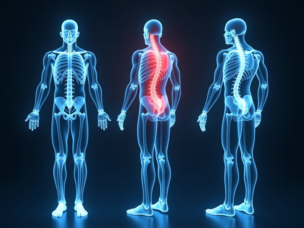
Oem Full Body Composition Analyzer
This device measures body composition using multi‑frequency bioelectrical impedance analysis (BIA) with eight tactile electrodes positioned for hand‑to‑foot and foot‑to‑hand pathways. The technique
Inquire NowOEM Full Body Composition Analyzer
This device measures body composition using multi‑frequency bioelectrical impedance analysis (BIA) with eight tactile electrodes positioned for hand‑to‑foot and foot‑to‑hand pathways. The technique sends low‑amplitude alternating currents through the body and evaluates the resulting impedance at frequencies ranging from 5 kHz to 500 kHz, enabling separate estimation of extracellular water, intracellular water, fat mass, and lean tissue.
Core Measurement Technology
Eight electrodes are arranged in a modular array: four on the handgrips and four on the footplates, each driven by a constant‑current source and sampled by a 24‑bit delta‑sigma ADC. Impedance is measured simultaneously at 5, 50, 100, 250, and 500 kHz, providing the spectral data needed for Cole‑Cole modeling and segmental analysis. The front‑end includes programmable gain amplifiers and active shielding to suppress motion artifacts and environmental noise.
Technical Specifications
| Parameter | Typical Value / Customizable |
|---|---|
| Measurement Frequencies | 5 kHz, 50 kHz, 100 kHz, 250 kHz, 500 kHz (user‑selectable) |
| Impedance Range | 100 Ω – 1000 Ω (auto‑ranging) |
| Current Excitation | ≤ 0.8 mA rms, IEC 60601‑2‑27 compliant |
| Output Interfaces | USB 2.0, RS‑485 (Modbus RTU), optional Bluetooth LE |
| Power Supply | 12 V DC external adapter, 2 A max |
| Operating Temperature | 0 °C – 40 °C, 10 % – 90 % RH non‑condensing |
| Enclosure Rating | IP40 (standard), IP65 available upon request |
Design for OEM Integration
The analyzer is supplied as a compact printed‑circuit assembly measuring 120 mm × 80 mm × 25 mm, with standardized M3 mounting holes on the baseplate for easy integration into kiosks, scales, or wearable housings. Firmware is delivered as a modular library exposing functions for impedance acquisition, parameter calculation, and data logging, allowing partners to embed proprietary algorithms or UI layers without modifying the hardware.
Material and Build Considerations
The electrode contacts use stainless‑steel 316L with a gold‑plated surface to reduce contact impedance and resist corrosion from sweat. The outer casing can be molded from ABS‑PC blend for impact resistance or from medical‑grade polycarbonate when biocompatibility is required. Internal PCB employs FR‑4 with a conformal coating to protect against humidity, and all connectors are keyed to prevent misalignment during assembly.
Application Scenarios
Fitness centers utilize the analyzer for member baseline assessments and progress tracking, relying on its segmental output to tailor training programs. In clinical environments, the device supports hydration monitoring for dialysis patients and sarcopenia screening in geriatric wards, where repeatability within ±1.5 % for fat‑free mass is critical. Corporate wellness programs benefit from the low‑maintenance design and quick (< 10 second) measurement cycle, enabling high‑throughput screening during health fairs.
Quality Control and Validation
Each unit undergoes a two‑point impedance calibration using precision resistors traceable to NIST standards, followed by a functional test against a reference dual‑energy X‑ray absorptiometry (DEXA) scanner on a cohort of 30 subjects with varying body types. Production lots are subject to statistical process control, with a target Cp > 1.33 for key parameters such as reactance at 50 kHz and phase angle at 5 kHz. Final inspection includes visual examination of electrode plating integrity and verification of firmware checksums.
Customization Options
- Selection of measurement frequencies (additional 1 kHz step or higher‑frequency bands)
- Alternate electrode layouts (hand‑only, foot‑only, or segmental arrays)
- Firmware feature toggles (athletic mode, clinical mode, research mode)
- Enclosure color, texture, and logo laser‑etching
- Alternative connector types (M12, JST, or custom flex‑cable)
- Packaging options: anti‑static trays, individualized boxes, or bulk pallets
Frequently Asked Questions
Can the dimensions be altered for enclosure integration? Yes, the PCB outline and mounting hole pattern can be adjusted within a ±5 mm range to accommodate specific housing designs; mechanical drawings are provided upon NDA signature.
What information is required before quotation? We need the intended measurement frequencies, desired output interfaces, enclosure material preference, estimated annual volume, and any regulatory certifications (e.g., FDA 510(k), CE MDR) that must be met.
How is quality inspected? Each unit receives automated impedance verification, visual inspection under 10× magnification for electrode plating, and functional validation against a reference device; inspection records are retained for traceability.
Contact for OEM Inquiry
To discuss technical feasibility, request a sample, or obtain a detailed quotation, please reach out to our engineering team. We will respond with a project‑specific feasibility report within two business days.