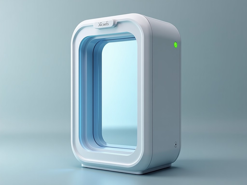
Custom 3D Body Scanning Mirror Supplier
A 3D body scanning system relies on precise optical mirrors to direct structured light or laser patterns onto the subject and capture reflected data. The mirror’s surface figure, reflectivity, and
Inquire NowCustom 3D Body Scanning Mirror Solutions
A 3D body scanning system relies on precise optical mirrors to direct structured light or laser patterns onto the subject and capture reflected data. The mirror’s surface figure, reflectivity, and environmental stability directly influence measurement accuracy and repeatability.
Technical Characteristics
Typical mirrors for body scanning are first‑surface coated to avoid double‑pass errors. Surface flatness is specified in fractions of a wavelength (λ) across the clear aperture, often λ/10 or better for high‑resolution scanning. Reflectivity in the visible spectrum (400‑700 nm) exceeds 95 % when protected with a durable overcoat.
Clear aperture dimensions are defined by the scanner’s field of view; common sizes range from 50 mm × 50 mm to 200 mm × 200 mm, with thickness typically between 6 mm and 12 mm to provide sufficient rigidity while minimizing weight. Edge blackening or masking reduces stray light.
Customization Options
- Substrate materials: BK7 glass, fused silica, or low‑expansion ceramics (e.g., Zerodur) selected based on thermal stability requirements.
- Coating choices: enhanced aluminum, protected silver, or dielectric multi‑layer stacks tuned to specific wavelength bands.
- Surface figure: λ/20, λ/10, or λ/5 peak‑to‑valley, measured with interferometry.
- Clear aperture shape: rectangular, circular, or custom contours to match scanner optics.
- Mounting features: threaded inserts, kinematic mounts, or adhesive bonding surfaces.
Typical Specification Table
| Parameter | Typical Range / Value | Notes |
|---|---|---|
| Substrate | BK7, Fused Silica, Zerodur | Selected per CTE and homogeneity needs |
| Clear Aperture | 50 mm × 50 mm – 200 mm × 200 mm | Custom shapes available |
| Surface Flatness (PV) | λ/10 @ 632.8 nm (typical) | λ/20 available for high‑precision |
| Reflectivity (400‑700 nm) | ≥95 % (enhanced Al) / ≥98 % (protected Ag) | Dielectric options >99 % at specific bands |
| Thickness | 6 mm – 12 mm | Balances rigidity and weight |
| Coating Durability | Protected overcoat, humidity resistance per MIL‑C‑48497A | Custom environmental specs on request |
Quality Control & Inspection
Each mirror undergoes interferometric surface figure measurement, spectrally resolved reflectivity testing, and visual inspection for coating defects. Dimensional tolerances are verified with coordinate‑measuring machines (CMM) to ±0.01 mm for mounting features. Documentation includes a test report summarizing roughness (RMS < 5 nm), wavefront error, and environmental conditioning results.
Applications in 3D Body Scanning
In structured‑light scanners, the mirror directs patterned illumination onto the torso or limbs and collects the deformed pattern for triangulation. Accurate wavefront preservation ensures that the projected fringes retain their spatial frequency, which directly impacts depth resolution. In laser‑based time‑of‑flight systems, low‑scatter mirrors maintain signal‑to‑noise ratio by minimizing diffuse reflections.
Because body scanning often occurs in ambient conditions with varying temperature and humidity, substrates with low coefficient of thermal expansion (CTE) and coatings resistant to oxidation help maintain calibration over extended production runs.
Ordering Information
To initiate a custom quote, provide the desired clear aperture dimensions, substrate material, coating specification, surface flatness tolerance, and any required mounting features. Sample production typically requires 3‑4 weeks after receipt of technical data, with lead times scaling with complexity and quantity.
Ready to discuss your custom 3D body scanning mirror needs?
Request Technical Consultation