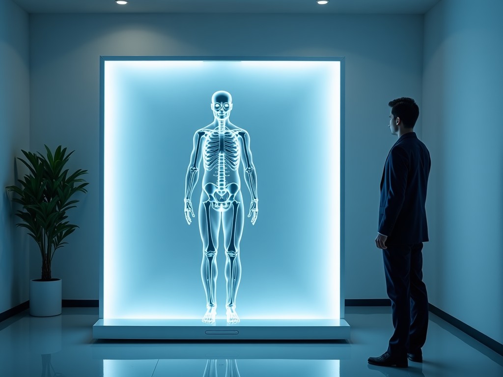
Advanced 3D Body Scanner Mirror Factory
This mirror directs structured light patterns onto the human body and captures the reflected signal for triangulation‑based 3D shape reconstruction. It is fabricated from a low‑expansion glass
Inquire NowAdvanced 3D Body Scanner Mirror System
This mirror directs structured light patterns onto the human body and captures the reflected signal for triangulation‑based 3D shape reconstruction. It is fabricated from a low‑expansion glass substrate with a precision‑figured surface and a reflective coating optimized for the scanner’s wavelength band.
Operating Principle
The scanner projects a known grating or dot pattern via a light source. The mirror redirects the pattern at a fixed angle so that it illuminates the target uniformly. Reflected light returns through the same optical path to a camera, where phase shift or triangulation computes depth.
Key Specifications
| Parameter | Typical Value | Unit | Notes |
|---|---|---|---|
| Substrate material | ULE® glass or Zerodur® | — | CTE <0.02 ppm/K |
| Clear aperture | 50 – 200 | mm diameter | Custom sizes available |
| Surface figure (PV) | ≤ λ/4 | @ 633 nm | Peak‑to‑valley |
| Surface roughness (Rq) | ≤ 0.5 | nm | Measured over 1 mm |
| Reflective coating | Enhanced Al + SiO₂ overcoat | — | Reflectivity >95% 400‑700 nm |
| Mounting interface | Kinematic flange or adhesive pads | — | Optional threaded inserts |
Material Selection & Construction
The substrate chooses a glass with near‑zero thermal expansion to maintain figure stability across temperature swings typical of factory environments. After fine grinding and polishing, an ion‑beam figured surface achieves the λ/4 PV specification before coating deposition.
A dielectric overcoat protects the aluminum layer from oxidation and enhances durability against cleaning solvents used in scanner maintenance. Edge blackening can be applied to reduce stray light.
Applications in Industrial 3D Scanning
In body‑scanning stations for apparel, the mirror ensures uniform illumination of the subject, which directly influences point‑cloud density and measurement repeatability. Consistent reflectivity across the visible band prevents colour‑dependent bias in phase‑shift algorithms.
Automotive ergonomics labs use the same optical path to capture driver posture; low scatter from the mirror’s surface reduces noise in the reconstructed mesh, allowing sub‑millimeter accuracy for clearance studies.
- Footwear fit analysis
- Virtual try‑on studios
- Medical prosthetic shaping
- Anthropometric research
Customization Options
Aperture diameter, shape (circular, rectangular, or custom contours), and thickness can be tailored to fit the scanner’s mechanical envelope. Coating alternatives include protected silver for NIR bands or dielectric stacks for specific laser lines.
Mounting features such as kinematic brackets, threaded inserts, or adhesive pads are defined per customer drawing. Surface treatments like anti‑reflection on the back side can eliminate ghost reflections.
- Diameter: 30‑250 mm
- Thickness: 5‑20 mm
- Coating: Al, Ag, dielectric high‑reflector
- Edge treatment: blackened, beveled, chamfered
Quality Assurance & Testing
Each mirror undergoes interferometric measurement (Zygo or equivalent) to verify PV and RMS figures against the agreed tolerance. Surface roughness is confirmed with a non‑contact profilometer over multiple locations.
Environmental tests include thermal cycling (−20 °C to +60 °C) and humidity exposure to ensure coating adhesion and substrate stability. A final visual inspection checks for scratches, digs, and edge chips under 10× magnification.
Lead Time, Packaging & Shipping
Standard lead time for a configured mirror is 4‑6 weeks after receipt of approved drawing and material confirmation. Expedited options are available for critical projects.
Parts are packed in individual antistatic bags, placed in foam‑lined cartons, and sealed with shock‑absorbing corner protectors. International shipments comply with ISPM‑15 wood‑packing regulations when applicable.
Frequently Asked Questions
Can the mirror diameter be customized?
Yes. Aperture sizes from 30 mm to 250 mm are routinely produced; larger diameters require special handling and are quoted case‑by‑case.
What wavelength bands are supported by the coating?
Standard enhanced aluminum coating covers 400‑700 nm. Optional protected silver extends usefulness to 800‑1200 nm, and dielectric stacks can be designed for specific laser lines such as 1064 nm.
How is the mirror mounted in the scanner?
Mounting options include kinematic flanges with three‑point adjustment, adhesive pads for low‑stress installation, or threaded inserts for direct bolting. The interface is defined in the drawing.
What documentation accompanies each part?
Each mirror ships with a measurement report showing surface figure, roughness, and reflectance at the design wavelength. A material certificate and coating lot traceability are included upon request.
Request Technical Quote