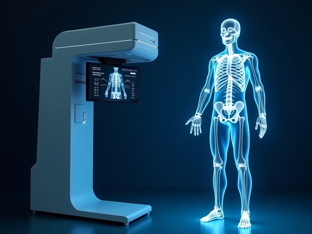
Oem Whole Body Scan Machine
A whole body scan machine provides rapid, non‑destructive imaging of large components or assemblies for internal defect detection. OEM configurations allow the scanner to be integrated into
Inquire NowOEM Whole Body Scan Machine
A whole body scan machine provides rapid, non‑destructive imaging of large components or assemblies for internal defect detection. OEM configurations allow the scanner to be integrated into production lines or customized for specific part geometries.
The system employs a fan‑beam X‑ray source paired with a flat‑panel detector that rotates around the stationary object, acquiring projection data from multiple angles. Reconstruction algorithms convert these projections into volumetric CT slices with adjustable voxel size. Typical spatial resolution ranges from 50 µm to 200 µm depending on detector pixel size and source‑to‑object distance.
Key Technical Specifications
The following table lists typical performance parameters; values can be adjusted according to project requirements.
| Parameter | Typical Value / Customizable |
|---|---|
| Scan Volume (max diameter) | 800 mm – 2000 mm (customizable) |
| Scan Volume (max length) | 1500 mm – 3000 mm (customizable) |
| X‑ray Tube Voltage | 80 kV – 450 kV (selectable) |
| X‑ray Tube Power | Up to 5 kW (configurable) |
| Detector Type | Amorphous silicon flat‑panel or CdTe (optional) |
| Pixel Pitch | 100 µm – 200 µm (selectable) |
| Frame Rate | Up to 60 fps (continuous mode) |
| Reconstruction Matrix | 512³ – 1024³ (adjustable) |
| Voxel Size | 50 µm – 200 µm (depends on optics) |
| Throughput | 10 – 60 parts/hour (application dependent) |
| Power Consumption | 8 kVA (typical) |
| Cooling Method | Water‑cooled chassis with optional air‑cooled variant |
| Control Interface | Industrial Ethernet (PROFINET/EtherCAT) with optional analog I/O |
Operating Principles
During a scan, the object remains fixed on a motorized table while the X‑ray source and detector assembly rotates 360° around it. Each projection captures attenuation data that is logarithmically transformed to linear absorption coefficients.
Filtered back‑projection or iterative reconstruction algorithms then produce cross‑sectional images. The scanner supports both continuous and step‑and‑shoot modes; continuous mode reduces scan time for uniform parts, while step‑and‑shoot improves signal‑to‑noise ratio for low‑density materials.
Typical Applications
Typical use cases span industries where internal integrity of large components is critical.
- Automotive chassis – detection of internal porosity and weld cracks in large frame assemblies.
- Aerospace landing gear – verification of internal heat‑treatment uniformity and foreign object debris.
- Heavy‑equipment castings – identification of shrinkage voids and core shifts in engine blocks.
- Energy sector – inspection of turbine rotors for fatigue cracks and material degradation.
Customization Options
The scanner can be tailored to meet specific part sizes, material densities, and integration constraints.
- Scanner aperture – adjustable diameter from 800 mm to 2000 mm to accommodate varying part sizes.
- X‑ray source – selectable voltage range 80 kV to 450 kV and power up to 5 kW for different material thicknesses.
- Detector – options include amorphous silicon flat‑panel with pixel pitches 100 µm to 200 µm or cadmium telluride for high‑density imaging.
- Software – modular reconstruction package with GPU acceleration, optional AI‑based defect detection, and API for MES integration.
- Safety enclosure – interlock‑controlled cabin with lead‑equivalent shielding thickness configurable per local regulations.
Quality Assurance and Testing
Each machine undergoes factory acceptance testing that includes spatial resolution measurement using a line‑pair gauge, low‑contrast detectability with a tungsten wire mesh, and geometric accuracy verification via a calibrated step phantom.
Radiation leakage is measured at all access points to confirm compliance with IEC 60601‑2‑44 limits. Software validation checks reconstruction accuracy against known phantoms before shipment. OEM buyers receive a test certificate summarizing key performance metrics and a traceable serial number for each major subsystem. Optional extended warranty includes periodic on‑site calibration and software updates.
Integration and Installation
The scanner is delivered as a modular skid‑mounted unit with standard ISO flange connections for power, data, and exhaust. Installation typically requires a reinforced floor capable of supporting the static load (up to 4 t) and dedicated three‑phase power supply (380‑500 V, 50/60 Hz).
Alignment lasers are included to facilitate table‑to‑source detector centering within 0.2 mm. Commissioning involves software configuration for part‑specific scan protocols, definition of reconstruction parameters, and safety interlock testing. Training for operators covers radiation safety, routine QA procedures, and troubleshooting of common artifacts.
FAQ
Common questions from industrial buyers are addressed below.
| Question | Answer |
|---|---|
| Can the scan volume be customized? | Yes, both diameter and length can be adjusted to match part dimensions; consult engineering for limits. |
| What information is needed for a quotation? | Part geometry, material density, required throughput, and any integration constraints (space, power, interfaces). |
| Which detector materials are available? | Amorphous silicon flat‑panel (standard) and cadmium telluride (high‑density option) are available. |
| How is quality inspected before shipment? | Factory acceptance tests include resolution, low‑contrast detectability, geometric accuracy, and leakage measurements per IEC standards. |
| What packaging methods are used for export? | Machines are sealed in shock‑absorbent crates with internal bracing and humidity‑indicating desiccants; optional ISPM‑15 compliant wood. |
| What is the typical lead time? | Lead time ranges from 12 to 16 weeks depending on configuration and factory schedule. |