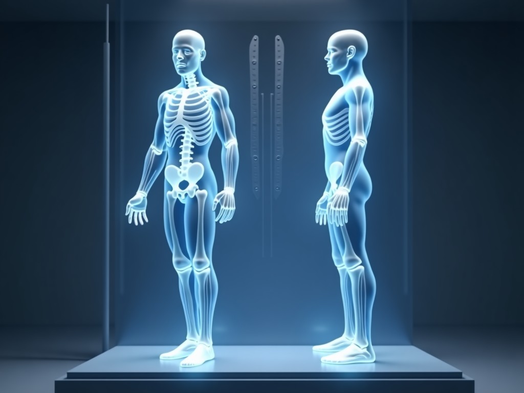
Oem Best 3D Scanner For Human Body
The device employs structured light projection with a dual‑camera system to capture surface geometry. Each frame consists of a coded pattern that enables sub‑millimeter depth calculation without
Inquire NowOEM Best 3D Scanner for Human Body
Overview of Scanning Technology
The device employs structured light projection with a dual‑camera system to capture surface geometry. Each frame consists of a coded pattern that enables sub‑millimeter depth calculation without physical contact. The scanning volume is defined by a 300 mm × 300 mm × 400 mm field of view, suitable for full‑body capture when mounted on a rotary platform.
Key Technical Specifications
| Parameter | Typical Value |
|---|---|
| Resolution (point spacing) | 0.2 mm |
| Accuracy (volumetric) | ±0.3 mm |
| Scan speed (single frame) | < 0.5 s |
| Working distance | 500 mm – 1500 mm |
| Weight (sensor head) | 1.2 kg |
| Power consumption | 12 W (typical) |
| Output formats | PLY, STL, OBJ, JSON point cloud |
| Interface | USB 3.0, GigE optional |
| Operating temperature | 0 °C – 40 °C |
Typical Applications in Industry
Capturing accurate body scans enables mass‑customization of apparel, reducing return rates caused by poor fit. In medical settings, the data supports prosthetic socket design and orthotic fitting with repeatable measurements. Entertainment studios use the scans for creating digital doubles in virtual reality and film production.
- Apparel manufacturers: virtual fitting rooms and made‑to‑measure garments
- Healthcare providers: custom prosthetics, orthotics, and compression garments
- Animation and gaming studios: high‑resolution character rigging
- Fitness and sports science: body composition tracking and ergonomic analysis
OEM Integration Capabilities
The scanner ships with a C‑based SDK that provides direct access to raw frame data, depth maps, and texture maps. Developers can embed the scanning pipeline into existing production lines or software platforms via the provided API, which supports Windows 10/11 and Linux x86_64. Mechanical mounting options include M4 threaded holes on the housing and a adjustable bracket kit for retrofitting onto conveyor systems.
Quality Control and Calibration
Each unit undergoes a factory calibration traceable to a NIST‑standard reference plane, verifying point‑to‑point accuracy across the full field of view. A built‑in temperature sensor triggers automatic gain adjustment to maintain performance within ±0.1 mm drift over the operating range. Final inspection includes a repeatability test using a calibrated artifact, with results stored in the device’s non‑volatile memory for OEM audit trails.
Frequently Asked Questions
Can the scanning volume be adjusted for different body sizes?
The field of view is fixed by the optics, but working distance can be changed within the specified range to capture larger or smaller subjects while maintaining resolution.
What materials are available for the enclosure?
The standard housing is aluminum alloy with anodized finish; alternative stainless‑steel or polymer composites can be supplied upon request for specific environmental conditions.
How is quality inspected before shipment?
Each scanner passes a three‑step check: optical alignment verification, accuracy validation against a gauge block, and functional test of the SDK interface.
What is the typical production lead time for OEM orders?
Lead time ranges from 4 to 6 weeks depending on customization level and current capacity; exact schedules are provided after technical review.