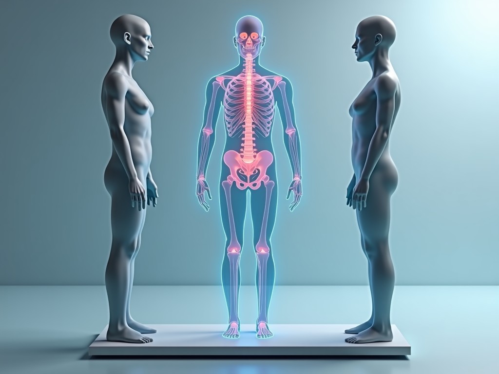
China Whole Body 3D Scanner
A whole body 3D scanner captures the external geometry of a human subject in a single, non‑contact pass. The resulting point cloud provides millimetre‑level detail usable for ergonomic analysis,
Inquire NowChina Whole Body 3D Scanner
A whole body 3D scanner captures the external geometry of a human subject in a single, non‑contact pass. The resulting point cloud provides millimetre‑level detail usable for ergonomic analysis, apparel design, and medical assessment.
Measurement Principle and Performance
The system uses structured light projection combined with high‑resolution CMOS sensors. Fringe patterns are deformed by the subject’s surface; phase‑shift algorithms convert these deformations into depth maps.
Typical specifications include a scanning volume of 2000 mm × 1000 mm × 600 mm, point spacing of 0.5 mm, and volumetric accuracy of ±0.2 mm. A full‑body acquisition completes in approximately 2 seconds.
Technical Specifications
| Parameter | Typical Value | Notes |
|---|---|---|
| Light Source | Blue LED, 460 nm | Stable intensity, low heat |
| Sensor Resolution | 2 MP global shutter | Enables high‑speed frame capture |
| Scanning Speed | 2 s per full body | Includes data transfer |
| Output Format | PLY, OBJ, STL | Compatible with CAD/CAE suites |
| Power Supply | 100‑240 VAC, 50/60 Hz | Auto‑ranging |
Typical Industrial Applications
In apparel manufacturing, the scanner supplies precise body measurements that drive pattern grading and reduce prototype iterations. Ergonomics labs use the data to assess workspace reach and posture, supporting design of workstations that minimise strain.
Medical researchers employ whole body scans to monitor morphological changes in rehabilitation or to create custom orthotics. The non‑invasive nature allows repeated sessions without discomfort or radiation exposure.
Key Advantages for Production Environments
- Non‑contact operation eliminates wear on delicate surfaces and avoids contamination.
- Sub‑second capture enables integration into high‑throughput lines.
- Point spacing of 0.5 mm yields sufficient detail for surface‑fit analysis while keeping file sizes manageable.
- Built‑in self‑calibration routine verifies accuracy before each shift.
Quality Assurance and Traceability
Each unit undergoes a factory acceptance test using a traceable artefact with certified dimensions. The test report includes deviation maps across the full field of view, ensuring that systematic errors remain within the specified ±0.2 mm envelope.
Field verification kits are available for periodic checks, allowing users to confirm performance against the original baseline without returning the equipment to the manufacturer.
Customization and Integration Options
Optional accessories include a motorised turntable for automated pose variation and a modular lighting kit for challenging surface finishes. Software bundles can add automated segmentation, mesh smoothing, or direct export to popular CAD platforms.
Integration with existing MES or PLC systems is supported via Ethernet/IP and Modbus TCP interfaces, enabling trigger‑based scanning synchronized with production cycles.
Frequently Asked Questions
Can the scanning volume be adjusted? The optical layout is fixed; however, optional lenses with different focal lengths are available upon request to alter the field of view while maintaining accuracy.
What file formats does the scanner output? Raw point clouds are saved as PLY; processed meshes can be exported as OBJ or STL directly from the control software.
How is the system calibrated? A built‑in reference panel is scanned at startup; the software compares the measured geometry to the panel’s certified dimensions and applies a correction matrix.